In this blog I will explain how I created a rain atmosphere effect by altering the URP Gbuffer. This is a second article in the Render Graph series. You can read the previous article here:
Render Graph API – Introduction
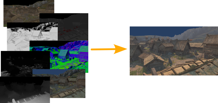
GBuffer
Before diving into the feature, I want to touch on what GBuffer is.
GBuffer is an array of textures containing various surface properties, like albedo, specular, smoothness, ambient occlusion, and emission. When you select the deferred rendering path in URP, Unity renders all scene objects into GBuffer. It means that instead of calculating the lighting at each draw, they output surface properties into GBuffer. Then, URP applies the lighting in the form of a postprocess.
URP GBuffer consists of 4 obligatory textures + some additional ones. According to URP documentation obligatory textures are:
GBuffer[0] – albedo in the RGB channels and material flags in the alpha channel.
GBuffer[1] – specular color in the RGB channels and ambient occlusion in the alpha channel.
GBuffer[2] – normal in the RGB channels and smoothness in the alpha channel
GBuffer[3] – the combined emission, GI, and lighting in the RGB channels.
The Render Deferred Lighting pass combines all the GBuffer textures and calculates dynamic lights.
How rain atmosphere can be achieved
To achieve the rain atmosphere effect, I need to manipulate the GBuffer content before the Render Deferred Lighting pass. I want to make the surface look wet after the lighting. But how do wet objects differ from dry objects? Here’s a photo illustrating the difference between dry and wet sand.
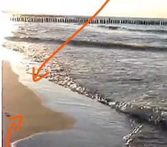
Wet surfaces appear darker and reflected light is sharp and bright. I can achieve that by reducing the intensity of albedo color and ambient light stored in the Gbuffer[0].RGB and GBuffer[3].RGB. Sharper reflections can be implemented by increasing the smoothness in the alpha channel in GBuffer[2].
To test the concept I adjusted material properties. I increased the smoothness and darkened the color. The visual impact matched what I hoped for.
Implementation
I broke the implementation into 3 steps:
- Set up the render feature
- Create the Render Graph pass
- Write the shader
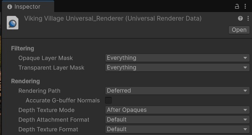
1. Setting up the render feature
First, I ensured that the project uses a deferred rendering path in the URP renderer settings. I disabled Accurate G-Buffer Normals as this option encodes the normal buffer differently. I want to use standard normal encoding to minimize complexity at this stage.
Then I started by implementing the Scriptable Renderer Feature. RainAtmosphereFeature injects the ApplyRainAtmospherePass into the render pipeline. ApplyRainAtmospherePass is set to be injected after rendering GBuffer by using a RenderPassEvent.AfterRenderingGbuffer. I will implement all rendering logic in the RecordRenderGraph method.
using UnityEngine;
using UnityEngine.Rendering;
using UnityEngine.Rendering.RenderGraphModule;
using UnityEngine.Rendering.Universal;

// This class is responsible for injecting the render feature into the URP renderer.
public class RainAtmosphereFeature : ScriptableRendererFeature
{
	// Material used for rendering
    public Material applyRainMaterial;

    private bool HasValidResources => applyRainMaterial != null;

	// This pass will handle the gbuffer modification
    private ApplyRainAtmospherePass applyRainAtmospherePass;

    public override void Create()
    {
        applyRainAtmospherePass = new ApplyRainAtmospherePass();
    }

    public override void AddRenderPasses(ScriptableRenderer renderer, ref RenderingData renderingData)
    {
        bool isGameOrSceneCamera = renderingData.cameraData.cameraType == CameraType.Game || renderingData.cameraData.cameraType == CameraType.SceneView;
        if (isGameOrSceneCamera && HasValidResources)
        {
	        // Update resources in the pass
            applyRainAtmospherePass.material = applyRainMaterial;

			// And add the pass to the renderer
            renderer.EnqueuePass(applyRainAtmospherePass);
        }
    }
}

// This class handles the rendering logic. Here I will build new nodes and insert them into RenderGraph.
public class ApplyRainAtmospherePass : ScriptableRenderPass
{
    public Material material { get; internal set; }

    public ApplyRainAtmospherePass()
    {
        this.renderPassEvent = RenderPassEvent.AfterRenderingGbuffer;
    }

    public override void RecordRenderGraph(RenderGraph renderGraph, ContextContainer frameData)
    {
        // TODO: I will implement the rendering logic here
    }
2. Creating the Render Graph pass
Here I will define a Render Graph pass that directly modifies the GBuffer contents.
URP shares the GBuffer between all passes. It means I can access it using frameData.Get<>() API. The GBuffer reference is stored in the UniversalResourceData.gBuffer and is only initialized when using a deferred path. Otherwise, it may not exist, or it can be set to a null handle. I need to check that before adding a custom node to the render graph.
public override void RecordRenderGraph(RenderGraph renderGraph, ContextContainer frameData)
{
    // Get GBuffer handles
    UniversalResourceData urpResources = frameData.Get<UniversalResourceData>();
    TextureHandle[] gBuffer = urpResources.gBuffer;

    // Check if GBuffer exists and if it is properly initialized (it will not be initialized in the forward path)
    if (gBuffer == null || gBuffer.Length == 0 || gBuffer[0].Equals(TextureHandle.nullHandle))
        return;
}
Once I confirmed GBuffer was valid, I proceeded with the node creation. I will modify GBuffer by executing a fullscreen procedural draw call to alter its contents. I created a raster graph node and a PassData class to store resources required in the render function. Then, I set GBuffer textures as render attachments of the node. GBuffer is an array of textures, so I used the for loop to bind all of them.
public override void RecordRenderGraph(RenderGraph renderGraph, ContextContainer frameData)
{
	UniversalResourceData urpResources = frameData.Get<UniversalResourceData>();
	TextureHandle[] gBuffer = urpResources.gBuffer;

	if (gBuffer == null || gBuffer.Length == 0 || gBuffer[0].Equals(TextureHandle.nullHandle))
		return;

	// Start creating a render graph node
	using (var builder = renderGraph.AddRasterRenderPass(GetType().Name, out PassData passData))
	{
		// Set all resources needed in a render function
		passData.material = material;

		// Set GBuffer as render attachment
		for (int i = 0; i < gBuffer.Length; i++)
			builder.SetRenderAttachment(gBuffer[i], i, AccessFlags.Write);
	}

}

// Resources used in the render function
internal class PassData
{
	// Material with the shader that will render the effect
	internal Material material;
}
For the render function, I kept it minimal: just a DrawProcedural call that uses my material. Since I’m rendering two triangles (a fullscreen quad), I drew 6 vertices. Each of the three consecutive vertices creates a triangle – two triangles in this case.
...
		for (int i = 0; i < gBuffer.Length; i++)
			builder.SetRenderAttachment(gBuffer[i], i, AccessFlags.Write);

		// Set render function
		builder.SetRenderFunc((PassData passData, RasterGraphContext context) => RenderFunction(passData, context));
	}
}

private static void RenderFunction(PassData passData, RasterGraphContext context)
{
	// Draw a procedural mesh. The mesh will be defined in a shader, so we specify that we want to render
	// 6 vertices as triangles using our material.
	context.cmd.DrawProcedural(Matrix4x4.identity, passData.material, 0, MeshTopology.Triangles, 6, 1);
}
...
3. Writing the shader
Now, I need to create a shader that will render into GBuffer. I must write a fragment shader that will output colors to three render targets. I prepared a basic shader that contains an empty vertex and fragment shader. We will work on these in the following steps.
Shader "Hidden/ApplyRainAtmosphere"
{
    SubShader
    {
        Pass
        {
            // Disable triangle culling
            Cull Off

            // Disable depth buffer usage
            ZTest Off
            ZWrite Off

            HLSLPROGRAM

            #pragma vertex vert
            #pragma fragment frag

            #include "Packages/com.unity.render-pipelines.universal/ShaderLibrary/Core.hlsl"

            void vert ()
            {
                // TODO: Draw a fullscreen quad here
            }

            void frag ()
            {
                // TODO: Modify GBuffer here
            }

            ENDHLSL
        }
    }
}
Vertex shader
The vertex shader’s main role is to define each vertex’s position on the screen. The position of the screen is defined in the Clip Space. In short, x,y defines the screen’s pixel, where (-1, -1) is one corner of the screen and (1, 1) is a second corner. z defines the depth. The position, as in float4, uses this format: (x*w, y*w, z*w, w).
Notice that when the w component is set to 1, the whole vector simplifies to (x, y, z, 1). We will use that trick in the next step.
In the render function, I declared drawing with six vertices, using two triangles. Each of the three consecutive vertices will form a triangle. The illustration below shows how the fullscreen mesh looks like.
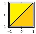
I stored those vertices in the constant array in the shader. I can access the ID of each vertex using the SV_VertexID semantic. This vertex shader outputs a fullscreen triangle. Here is what the code looks like:
// Fullscreen rectangle in clip space
static const float4 verticesCS[] =
{
	float4(-1.0, -1.0, 0.0, 1.0),
	float4(-1.0, 1.0, 0.0, 1.0),
	float4(1.0, 1.0, 0.0, 1.0),
	float4(-1.0, -1.0, 0.0, 1.0),
	float4(1.0, 1.0, 0.0, 1.0),
	float4(1.0, -1.0, 0.0, 1.0)
};

void vert (uint IN_VertexID : SV_VertexID, out float4 OUT_PositionCS : SV_Position)
{
	// Output the rectangle to clip space
	OUT_PositionCS = verticesCS[IN_VertexID];
}
Blending
Shader will target GBuffer0, GBuffer2, and GBuffer3, corresponding to albedo, normal-smoothness, and ambient light. In Unity shaders, I can specify the blending operation for each target texture using a Blend keyword at the beginning of the pass.
Each respective value produced by the fragment shader will affect the GBuffer with its blend operation. This is how I configured the blending for those targets.
GBuffer0 = ShaderOutput0 * GBuffer0
GBuffer2 = ShaderOutput2 + GBuffer2
GBuffer3 = ShaderOutput3 * GBuffer3
...
ZTest Off
ZWrite Off

// Multiply blending for albedo
Blend 0 DstColor Zero
// Additive blending for normal-smoothness
Blend 2 One One
// Multiply blending for ambient light
Blend 3 DstColor Zero

HLSLPROGRAM
...
Fragment Shader
Now its a time to make the fragment shader output values into GBuffer. This is done using the SV_Target<ID> semantics. For example, I reduced the albedo and ambient light color by half and add 0.7 to the smoothness.
void frag
(
out float4 OUT_GBuffer0 : SV_Target0,
out float4 OUT_GBuffer2 : SV_Target2,
out float4 OUT_GBuffer3 : SV_Target3
)
{
// Multiply blending - reduce colors by half, but leave the alpha channel as is.
OUT_GBuffer0 = float4(0.5, 0.5, 0.5, 1.0);
// Additive blending - leave normals in RGB as is, but add 0.7 to smoothness.
OUT_GBuffer2 = float4(0.0, 0.0, 0.0, 0.7);
// Multiply blending - reduce colors by half, but leave the alpha channel as is.
OUT_GBuffer3 = float4(0.5, 0.5, 0.5, 1.0);
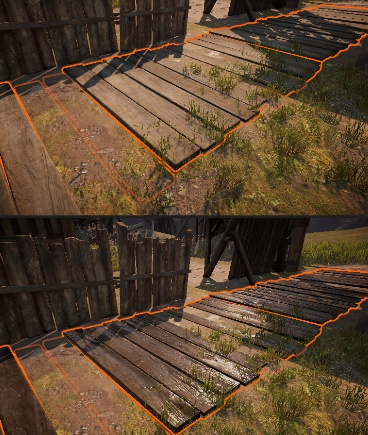
}Result
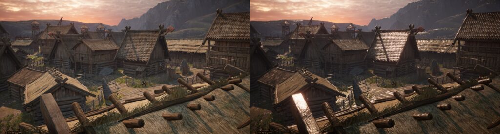
Shader is ready. It’s time to create a material with it and assign it to the render feature. You can see that my feature is working correctly. I was so used to the old look of the Viking Village, it is nice to have something fresh!
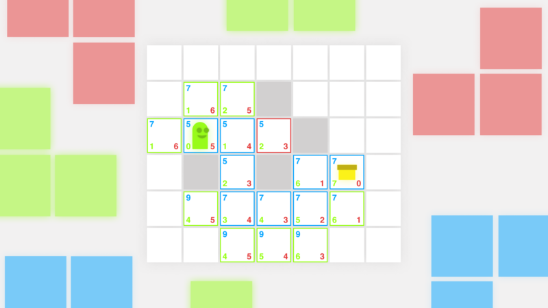
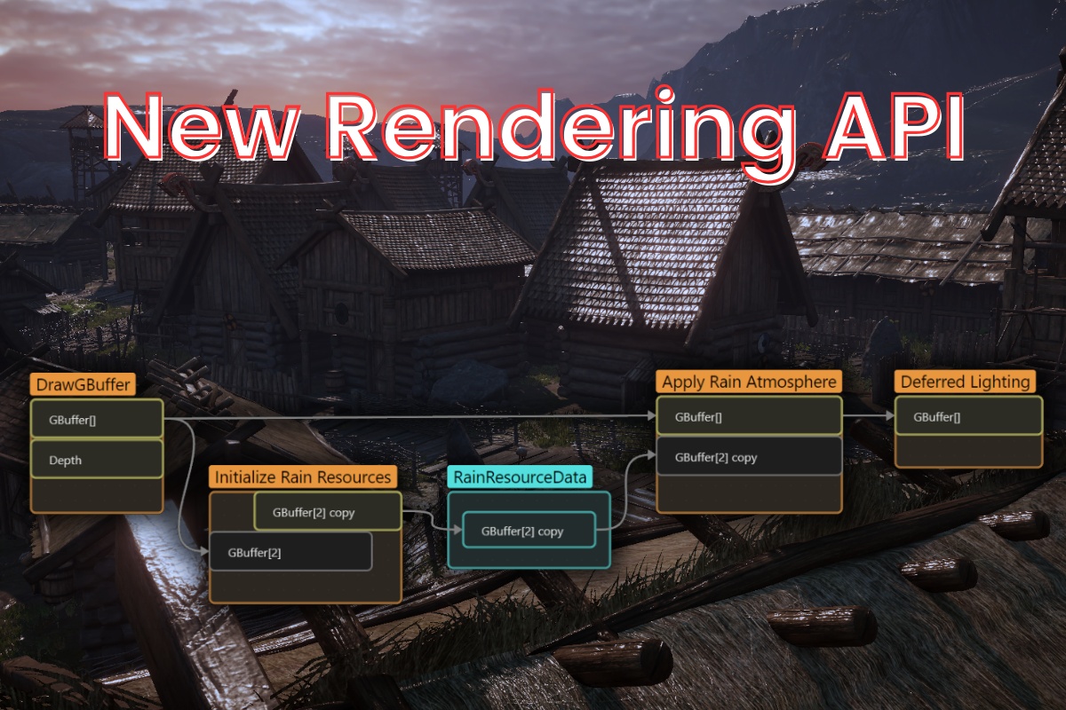
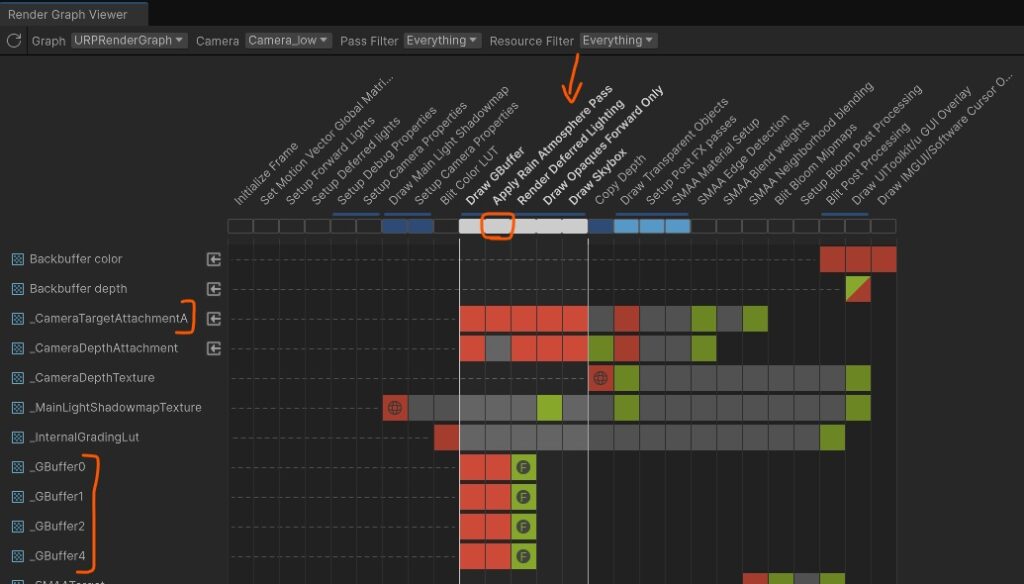
It is also displayed by the Render Graph Viewer (Window/Analysis/Render Graph Viewer) between Draw GBuffer pass and Render Deferred Lighting.
In the next article I will fix the bloom flickering caused by the high smoothness. I will also implement the parameters to control the visuals.
About the author
Jan Mróz / Sir Johny – Graphics Programmer at The Knights of U. He specializes in rendering pipeline extensions and performance optimization across CPU, GPU, and memory. Sir Johny also leads tech-art initiatives that improve visual quality while cutting iteration time.
Learn more from Jan at proceduralpixels.com.